Fiat Lux!
<-- Blinkenlights | Driving a VFD with the HV5812 -->
Having gotten the microcontroller powered up and the toolchain going, it was time to get the VFD tubes lit up, or at least one of them. I did the MCU first mostly because I wanted an opportunity to get to know my new used power supply on something expendible. I bought an extra one when I placed my Digikey order; I figured it’d be handy to have around if I blew one up. I was not keen on the idea of discovering some quirk in my ancient power supply by blowing up a $34 VFD.
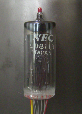
The VFDs are NED LD8113s. That’s printed right on the back of the tube. With that, I was hoping to find a datasheet online, but if it exists, I didn’t see it. Also, it’s probably in Japanese. A little digging turned up the EEVblog forums. I learned a few things there.
The simplest possible VFD has 2 things: 1) A filment, and 2) the segment anodes. VFDs that are meant to be multiplexed also have a control grid. That much is on Wikipedia.
The EEVblog forums gave me a little more information about actually lighting these up. First and foremost, the filament is typically driven by low voltage AC. This can range from 1 to 5 volts, depending on the tube. You can also drive the filament with a low voltage DC without harming the tube. In some tubes that results in a visible difference in brightness level from one side of the tube to the other, but if I don’t see a difference, I’m not going to muck around with AC in the finished clock.
Secondly, the anodes and grid need to be hooked up to somewhere in the +10V to +30V to light up the segments.
The required filament voltage varies too, from 1V to 5V depending on the tube. The filaments will survive being driving a little harder than they should be. Too hard and they’ll blow. Generally speaking, they’ll survive being heated to the point of visibly glowing, but probably shouldn’t be driven like that in regular use.
With all of this in mind, I connected one of my tubes to my breadboard. If you look closely at the picture above, you’ll see a yellow insulator on one of the leads, and red inuslators on two of them. The red leads are the filaments. A neat thing about the filaments is that they’re made of tungsten, and a neat thing about tungsten is that its resistance goes up as it heats up. Without power applied, the filament measures about 6 ohms, but it goes up as you increase the voltage.
I measured the voltage across the filament and the current passing through it at varying voltages to figure out how much resistance I’d see in operation:
| Voltage (V) | current (mA) | calculated resistance (Ω) |
|---|---|---|
| 1.12 | 71.5 | 15.7 |
| 1.32 | 73 | 18.1 |
| 1.54 | 84 | 18.3 |
| 1.68 | 88 | 19.1 |
| 2.09 | 99 | 21.1 |
At 2.1 V, the filament was visibly glowing in ambient light, so I stopped bumping the voltage. Dialing the voltage back to 1.5V resulted in a faint glow in a dark room. That seems like a reasonable level for now.
I’m running that logic at 5V, and a little math indicated that I needed a 42 ohm resistor to hit my target voltage drop across the filament. A 47 ohm and 330 ohm resistor in parallel give me ~41 ohms. Close enough.
With all of the confidence in my calculations that having taken physics 122 a dozen years ago inspires, I decided to power this from my bench power supply and ramp the voltage up until I hit 5V while monitoring the filament voltage with my DMM. It would be $34 to find out that my math was wrong, after all. Happily, I got to 5V without incident, and so I hooked the filament circuit up to the 5V bus and carried on.
I was careful to pick a voltage regulator that would run on voltages in the voltage range required by the anodes and girds. The one I have will happily run on 8V to 28V, so I was free to try that range to light up the VFD. At 12V, they look nice, at 24V, they’re quite bright.

With all of this experimentation, I have a few loose ends to tie up as far as design for the final clock goes:
- The 1/4 W 47 ohm resistor is actually dissipating .26 W in this configuration. I’m just going to live with this while it’s on the breadboard, but I’ll need to do something on the final clock.
- The DC voltage regulator I’m using is good to supply 500mA. 84 mA / tube * 4 tubes = 336 mA just to run the filaments if I run them all in parallel.
Possible options for the final clock:
- Maybe 164 mA will be enough to run the MCU and other logic?
- If I’m just shy, maybe drop the filament voltage a bit?
- Put in a second DC regulator and run two filaments on each regulator.
- Run the filaments in two parallel circuits of two tubes and 12 ohms of resistance each.
The first three options will require a 1/2 W 47 ohm resistor instead of the 1/4 W ones I’m using now. I’ll be curious to see if the last option results in a visible difference in brightness between the two tubes in series. For just one tube, I don’t see any.