Blinkenlights
<-- So I have these VFDs... | Fiat Lux! -->
Before trying to figure out how to light up the VFDs, I figured I’d get the microcontroller up and running. Easier said than done. Wiring everything up was easy enough; it doesn’t take much to blink an LED: VCC, GND, AVCC, the other GND, pull RST high, and provide a way to connect the programmer.
Prior to providing a way to connect a programmer, I had this:
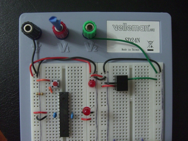
The switching regulator is on the right. All of the logic will run on 5V supplied by the regulator, and the regulator will be supplied by the same voltage that the VFDs grids and segments require.
I soldered up some wires and pin headers, hooked the microcontroller up and fired up avrdude:
[ediven@rangeley ~]$ avrdude -c usbtiny -p atmega328
avrdude: Warning: cannot open USB device: Permission denied
avrdude: Error: Could not find USBtiny device (0x1781/0xc9f)

avrdude done.  Thank you.

[ediven@rangeley ~]
After I added myself to the sudoers file, I got avrdude talking to the mcu:
[ediven@rangeley ~]$ sudo avrdude -c usbtiny -p atmega328

avrdude: AVR device initialized and ready to accept instructions

Reading | ################################################## | 100% 0.01s

avrdude: Device signature = 0x1e9514

avrdude: safemode: Fuses OK (E:07, H:D9, L:62)

avrdude done.  Thank you.

[ediven@rangeley ~]$
Great. Now to blink that LED. I wound up finding SparkFun’s blink code, but missing the Makefile. So I gamely tried rolling my own based on various snippets I’d seen online:
BIN=blink
OBJS=blink.o

PROCESSOR=atmega328
PROGRAMMER=usbtiny

CC=avr-gcc
OBJCOPY=avr-objcopy
CFLAGS=-Os -DF_CPU=1000000UL -mmcu=$(PROCESSOR)

$(BIN).hex: $(BIN).elf
	$(OBJCOPY) -O ihex -R .eeprom $< $@

$(BIN).elf: $(OBJS)
	$(CC) -o $@ $^

install: $(BIN).hex
	sudo avrdude -V -c $(PROGRAMMER) -p $(PROCESSOR)  -U flash:w:$<

clean:
	rm -f $(BIN).elf $(BIN).hex $(OBJS)
make install and … nothing. If this isn’t your first rodeo, you may have spotted the issue already. Wanting to rule out the chip not being programmed correctly, I started avrdude in interactive mode and dumped the first however many bytes of memory. Upon confirming that they matched the .hex file I’d programmed to the chip, I wondered what the zeroes and ones on the chip actually were. I ran nm on blink.elf and soon found my answer:
00000000 T ioinit
The ioinit() function is located at address 0x0? That seems fishy. The datasheet confirms that address 0x0 should be the reset handler. It looks like a missing linker option. A little more Googling turned up Ladyada’s Blinky tutorial. Her tutorial is on Windows, but she’s using the same toolchain and has screenshots from the build process. With a little bit of -mmcu=atmega328 here and some $(LDFLAGS) there, I got blinking.
See the code here