Shady Characters
<-- Driving a VFD with the HV5812 | A build system -->
At this point, it’s time to make the VFD tube display something useful, or at least interesting. I only have one hooked up to the breadboard, but I’d like to at least get some of the groundwork done for driving the finished clock. The code is still a little rough, but I hope to be able to pull out some of the basic building blocks and reuse them.
In order for the code to make sense, I probably need to go into how I’m hooking all this up on the (yet to be fully designed or laid out) PCB. Each of the VFDs has 3 basic parts:
- A filament
- A bunch of anodes that make up the segments
- A grid between the filament and the anodes that contols whether the anodes are active
The filaments are straightforward; there’s no logic to control them. They’re always on because they’re slow to heat up enough for the display to become useful (several seconds).
The segments will be driven by the HV5812 as discussed previously. Each segment is hooked to one output from the HV5812.
The grids will be driven by the high voltage driver chip, and they’re what will let me multiplex the tubes in a 2x2 configuration.
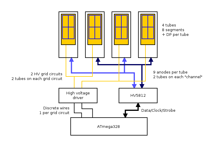
The choice of a 2x2 configuration is pretty simple. The HV5812 has 20 channels of output and each tube has nine anodes. That means I can drive two VFDs per HV5812 controller. I could either put 2 HV5812s in the clock, or I could put one HV5812 in and a high voltage driver and multiplex them. I decided that it would be more interesting to go with the multiplexing option.
As an added bonus, you aren’t supposed to hook the HV5812 up to a high voltage supply until after you get the various logic level inputs into a known state. I’ve been ignoring that with no apparent ill effects to either the controller or the tube other than the controller coming up with unpredictable outputs. In the finished clock, I’ll supply the HV5812 with high voltage switched through the high voltage driver.
The finished clock will have four VFD tubes set up in groups of two. Both groups of two will be connected to the same HV5812 controller, and each group will be connected to a separate grid circuit driven by the high voltage driver. Below, the worst block diagram ever illustrating this:
That’s the hardware. The software controlling it all is as follows:
The HV5812 controller is probably the easiest place to start. I’m using 3 of its inputs: DATA_IN, CLK, and STROBE. There’s also an input for blanking that I could PWM to control brightness of the display, but if I decide to implement that, I’ll do it with the grid circuits. The controller has 20 outputs, which will logically be divided into 2 channels, with two tubes on each. I plan to drive the controller on GPIO pins.
The controller doesn’t actually have channels, and the final mapping of controller output to segment will depend more on what lays out nicely than anything. For this reason, the mapping could vary on a per-tube basis.
In the software, the tubes are represented by a struct containing pointers to both the controller and grid that it’s connected too. It also contains the segment map, which maps each segment in the tube to an output on the controller its connected to.
The grids are a little more interesting in that the structure representing them contains some state. Besides an array of pointers to the two tubes that are on the grid and the controller, I’ve also included the data that needs to be sent to the controller before making the grid active. It seems unnecessary to recompute this every time I switch between grids since, in the final clock, it’s only going to change once a minute in the common case.
The whole display is represented in a structure that contains an array of tubes in visual (left to right) order and another containing the grids in no particular order. For the final clock, this will also need to keep track of which grid is active so that I know which grid is active and which is the next one to make active in the multiplexing code.
I keep going on about segments. The segments are defined as a pair of enums: One enum defines the shift of the bit representing each segment in a uint16_t, the other is the shifted value itself. The segment shift also happens to be the index into the array that maps segments to outputs on the HV5812 VFD controller.
Each character is a uint16_t, of which I’m using only the 9 least significant bits to represent the 8 segments and the decimal point. Turning a (character, tube) tuple into data I can send to the controller is a simple matter of iterating over the segment shifts, testing the corresponding bit in the character, and if it’s set, setting the corresponding bit in the data to be sent to the controller.
As for what I can actually represent on the tubes, I’ve got full coverage of the numbers and all of the letters except for K, V, X, and Z. The letters vary in case, S is the same as 5, and Q is wonky, but they’re readable. To avoid special-casing the unrepresentable characters in the code that turns character data into controller data, I’ve put in a substitution character into the array of letters. It’s the segments making up the letter H plus the vertical bar. It looks a bit like the International Harvester logo.
There’s more to be done to get the diplay code fully worked out for the finished clock. For now, I have enough to use to hook up the realtime clock chip. Once I have that I’ll do the layout and order boards since they’ll have a long lead time. I’ll get the display code in more-or-less final form during that time and also make some provisions for setting the time on the clock itself.
The code is on github here
But enough of that. Let’s see a proper “Hello world”: